| Sequence of operations: |
| |
| 1. Fast approach |
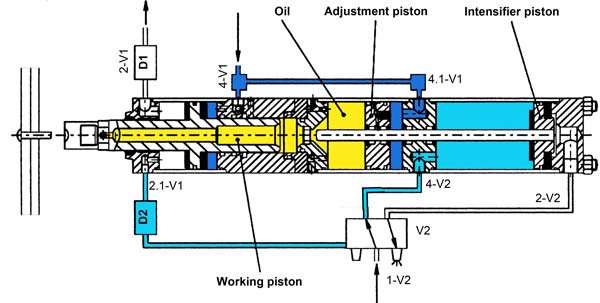
| Connection point 4-V1 pressure admitted, connection
point 2-V1 vented. The working piston and the adjustment piston extend with low
force and with high speed. Due to the impact pressure via 2.1-V1 valve V2 is held
in its initial position. Valve V1 supplied from customer, here not displayed. |
|
|
| |
| 2. Begin power stroke |
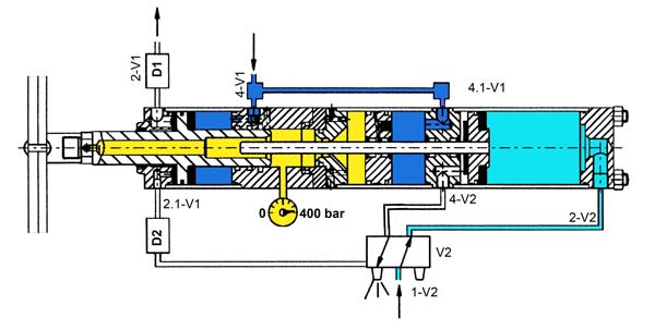
| The working piston hits resistance and the impact
pressure is released via throttle D2. Valve V2 switches over. The intensifier
piston passes through the high pressure seal and divides the hydraulic connection
between adjustment piston and working piston. |
|
|
| |
| 3. Power stroke |
| Pressure or power intensification takes place. Compared
to the intensifier piston, the working piston moves out with increased force,
reduced speed, and reduced stroke length (power stroke). |
|
|
| |
| 4. Return stroke |
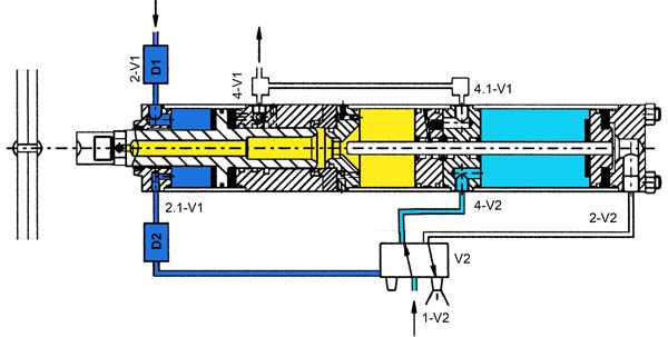
| Connection point 2-V1 is pressure admitted. Connection
point 4-V1 is vented. Working piston and intensifier piston move fast towards
their initial position at the same time. As soon as the intensifier piston opens
the hydraulic connection between the working piston and the adjustment piston,
the adjustment piston is oil pressure admitted and moves together with the working
piston back to their initial position. |
|
|
| |
| |
| Advantages: |
- Operates only with air, without hydraulic power units
- High travel stroke force, because of pressure applied to the working- and
adjustment piston
- Fast, air-operated approach stroke and return stroke
- Automatic change-over from approach stroke to power stroke
- High stroke frequency, depending on the stroke length
- Absolute air / oil separation for trouble-free operation
- Compact cylinder design, which can be used in any mounting position
- Standard high pressure measuring and control connection
- No oil in the working area
- Controlled through standart pneumatic 5/2-way valves
- Low maintenance. Smooth operation protects attached tools
- Reduced noise level
- Energy saving, minimal air consumption (compared to pneumatic cylinders up
to 80%)
- No spring inside of the cylinder which will be compressed
and released during each operation cycle. Springs applied with high stroke frequencies
have a limited life expectation and will destroy the cylinder when breaking.
|
| and therefore: |
- No counter force onto the intensifier piston during the power stroke.
- Function of the cylinder already with 2 bars.
- Continuous pressure onto the intensifier piston during the return stroke,
pressure and speed adjustable.
- Highest life expectation of the cylinder. Hydraulic and pneumatic seals from
leading manufacturers.
- Minimal air consumption through MULTIPOWER standard controls
- Return stroke of intensifier piston achieved only with 2 bars air pressure.
|
| cross section |
|
|