| |
Versions
| |
| |
Diagram, valid for all types and sizes |
|
| |
| Versions |
10-bar-version
8-bar-version
6-bar-version
|
 |
| |
| |
| signifies: |
|
| |
| 100 % of the rated force ( F power stroke) at: |
| |
10-bar-air pressure
8-bar-air pressure
6-bar-air pressure
|
| |
|
| |
| Declaration of forces for MULTIPOWER type G: |
| |
cylinder-size
|
not dependent on stroke length
|
power stroke length
0 - 12 mm
|
power stroke length
13 - 24 mm
|
power stroke length
25 - 44 mm
|
 |
|
|
|
|
G 20 |
|
G 40 |
|
G 60 |
|
G 80 |
|
G 150 |
|
G 300 |
|
G 500 |
|
G 750
|
|
G 1000 |
|
|
at 10 bar air pressure
|
|
F approach stroke
kN
|
F return stroke
kN
|
|
2,65
|
2,52
|
|
3,75
|
3,34
|
|
4,82
|
4,24
|
|
6,67
|
5,63
|
|
10,43
|
9,27
|
|
17,08
|
15,87
|
|
21,62
|
20,09
|
|
32,29
|
27,13
|
|
41,70
|
37,09
|
|
|
at 10 bar air pressure
|
|
F power stroke
kN
|
|
21,1
|
|
41,2
|
|
59,9
|
|
78,9
|
|
151,8
|
|
319,7
|
|
498,5
|
|
736,6
|
|
975,1
|
|
|
at 10 bar air pressure
|
|
F power stroke
kN
|
|
20,8
|
|
41,2
|
|
63,3
|
|
78,9
|
|
158,8
|
|
322,5
|
|
451,6
|
|
759,7
|
|
|
at 10 bar air pressure
|
|
F power stroke
kN
|
|
20,8
|
|
41,2
|
|
(*) 62,9
|
|
82,5
|
|
160,2
|
|
292,5
|
|
471,8
|
|
| |
 |
| |
|
|
|
|
G 20 |
|
G 40 |
|
G 60 |
|
G 80 |
|
G 150 |
|
G 300 |
|
G 500 |
|
G 750
|
|
G 1000 |
|
|
at 8 bar air pressure
|
|
F approach stroke
kN
|
F return stroke
kN
|
|
2,12
|
2,02
|
|
3,00
|
2,67
|
|
3,86
|
3,39
|
|
5,34
|
4,51
|
|
8,34
|
7,42
|
|
13,67
|
12,70
|
|
17,30
|
16,07
|
|
25,84
|
21,70
|
|
33,36
|
29,67
|
|
|
at 8 bar air pressure
|
|
F power stroke
kN
|
|
20,2
|
|
(**) 43,1
|
|
63,6
|
|
80,3
|
|
147,0
|
|
324,4
|
|
492,7
|
|
734,8
|
|
949,2
|
|
|
at 8 bar air pressure
|
|
F power stroke
kN
|
|
22,9
|
|
41,9
|
|
61,3
|
|
76,2
|
|
(**) 150,6
|
|
318,1
|
|
450,1
|
|
749,4
|
|
|
at 8 bar air pressure
|
|
F power stroke
kN
|
|
20,9
|
|
39,7
|
|
(**) 62,7
|
|
83,1
|
|
157,6
|
|
290,8
|
|
459,0
|
|
| |
 |
| |
|
|
|
|
G 20 |
|
G 40 |
|
G 60 |
|
G 80 |
|
G 150 |
|
G 300 |
|
G 500 |
|
G 750
|
|
G 1000 |
|
|
at 6 bar air pressure
|
|
F approach stroke
kN
|
F return stroke
kN
|
|
1,59
|
1,51
|
|
2,25
|
2,00
|
|
2,89
|
2,54
|
|
4,00
|
3,38
|
|
6,26
|
5,56
|
|
10,25
|
9,52
|
|
12,97
|
12,05
|
|
19,38
|
16,28
|
|
25,02
|
22,25
|
|
|
at 6 bar air pressure
|
|
F power stroke
kN
|
|
18,6
|
|
41,7
|
|
(***) 61,4
|
|
80,0
|
|
137,0
|
|
290,0
|
|
470,2
|
|
709,4
|
|
1008,9
|
|
|
at 6 bar air pressure
|
|
F power stroke
kN
|
|
20,6
|
|
41,7
|
|
56,9
|
|
70,7
|
|
143,4
|
|
303,0
|
|
434,2
|
|
796,8
|
|
|
at 6 bar air pressure
|
|
F power stroke
kN
|
|
20,6
|
|
36,9
|
|
59,6
|
|
74,0
|
|
149,8
|
|
279,9
|
|
487,5
|
|
|
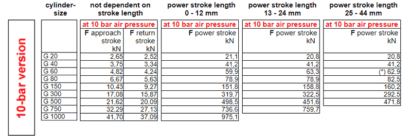
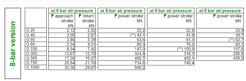
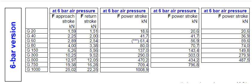
*) at a maximum air pressure of 9,5 bar
**) at a maximum air pressure of 7,5 bar
***) at a maximum air pressure of 5,5 bar
|
| |
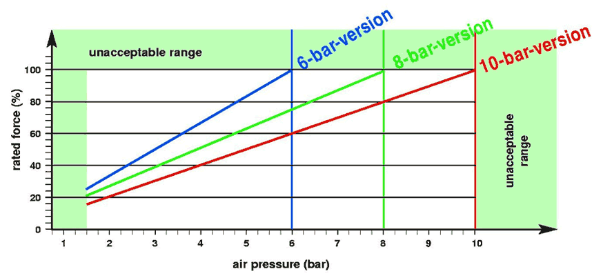
According to the diagram the force in the power
stroke, the approach stroke and the return stroke is linear to the input
air pressure.
Example: |
cylinder, 10-bar-version, size G 150 with a power
stroke length of 10 mm
|
| |
at 10 bar air pressure: |
151,8 kN force |
| |
at 1 bar air pressure: |
15,18 kN force |
| that means: |
at 6 bar air pressure: |
91,1 kN force |
|
|
| |
| |
|
| |
|
|